
Heap Leach Pad Dimensions
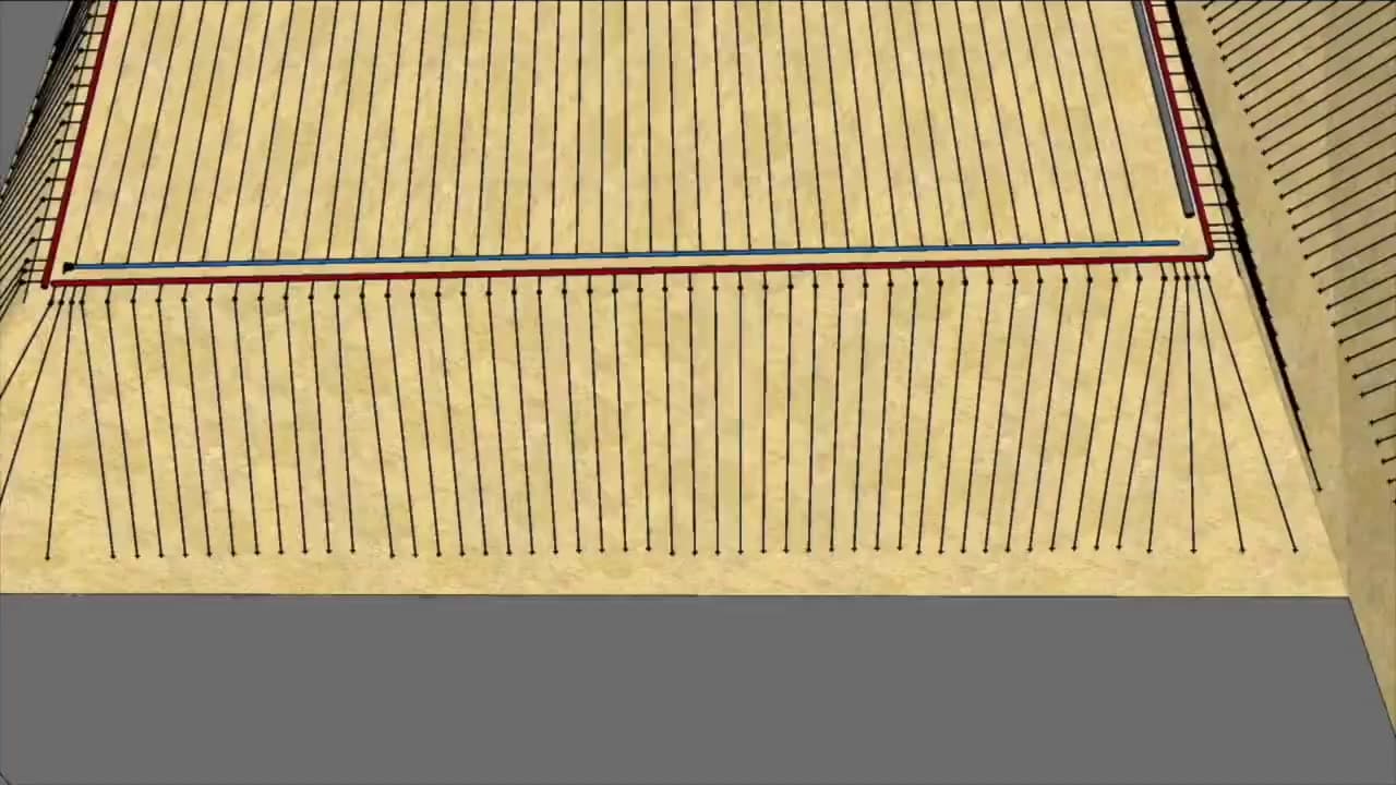
Length, width, lift height, and side slope angles — including any phased expansion plans for future lifts.
System Design Guide
Step 1
The first step is to compile all relevant data about your heap leach project. The more detailed the information, the more optimized your system design will be.
Length, width, lift height, and side slope angles — including any phased expansion plans for future lifts.
Mineralogy, agglomeration status, and crush gradation (e.g., agglomerated copper ore, 1/2 inch minus).
Solution application rate in L/h/m² or gal/h/ft², along with target leach cycle duration.
Acid concentration, pH, cyanide levels, oxidizers, and any aggressive constituents that affect material selection.
TDS, suspended solids, hardness, iron, and other contaminants that drive filtration and emitter selection.
Location of pump station, ponds, and heap pad — plus elevation deltas that drive pressure regulation strategy.
Max-Emitterline
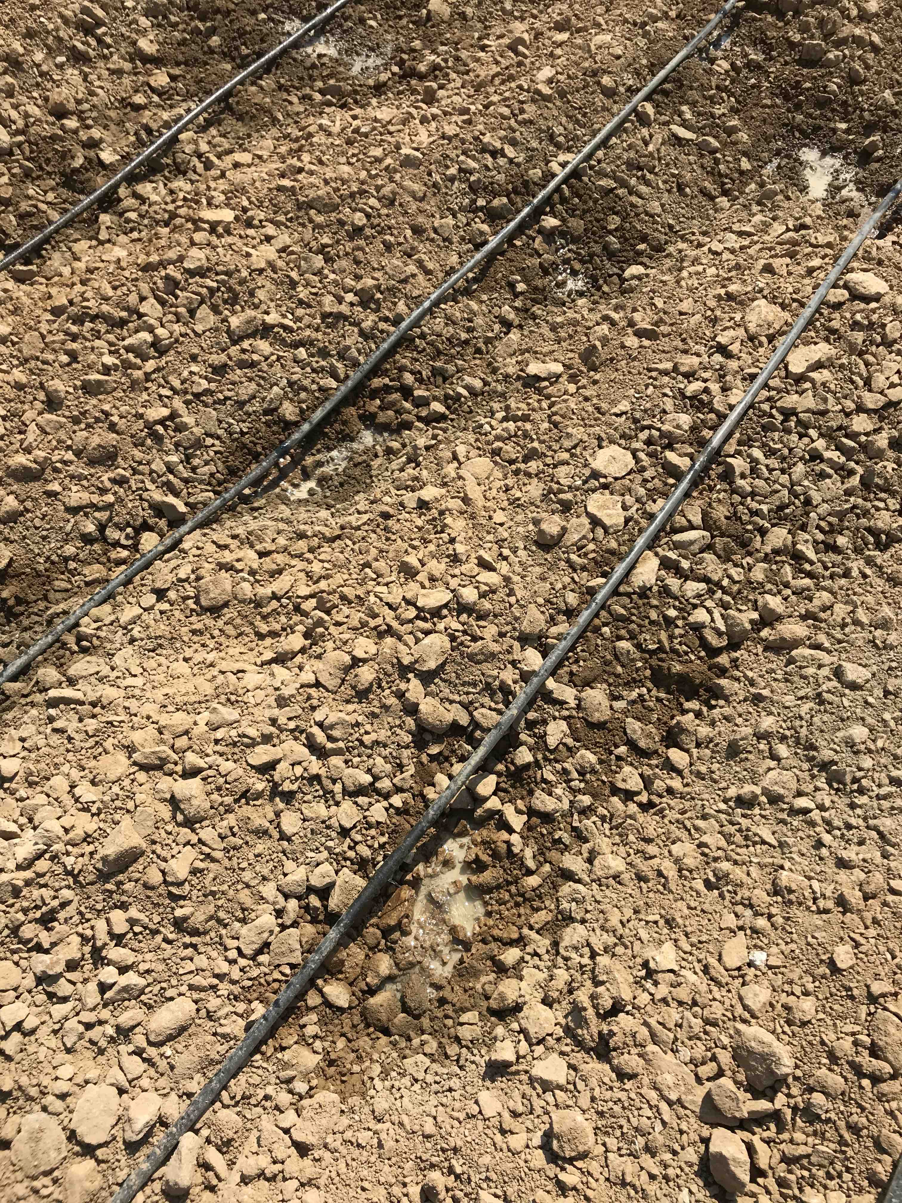
Engineered for heap leach
Diameter · Flow rate · Spacing
Step 2
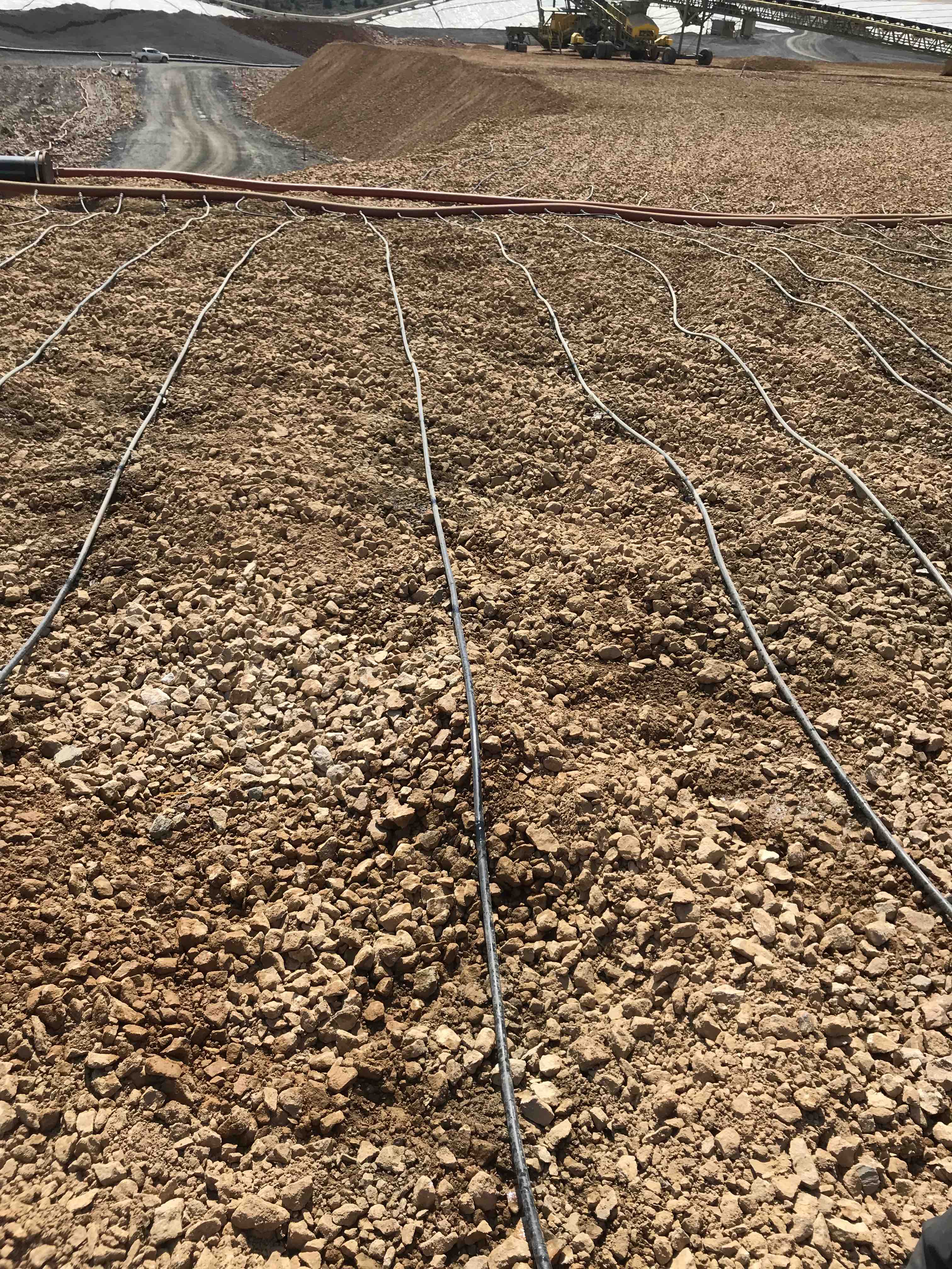
Based on your project data, our engineers will recommend the optimal emitterline diameter, flow rate, and spacing — balancing run length, application uniformity, and ore permeability.
Diameter (16 mm vs. 20 mm)
Sets the maximum single-run length while maintaining pressure. 20 mm allows for longer runs than 16 mm on the same pad geometry.
Flow Rate (1.5 to 8 LPH)
Matched to ore infiltration capacity and target application rate. Higher flow rates are used for more permeable ores.
Emitter Spacing
Distance between emitters along each line (18", 24", 36"). Closer spacing yields more uniform wetting — essential for less permeable ores.
Step 3
A complete system requires pipes, fittings, valves, and pressure regulators to control and distribute solution from pump to plug.
Our engineering team will produce a full bill of materials for your project, including mainline and submain pipes, pressure regulators to manage elevation changes, isolation valves for zone control, and all required fittings, connectors, and end plugs. You can browse these components in our product catalog.
Browse System Components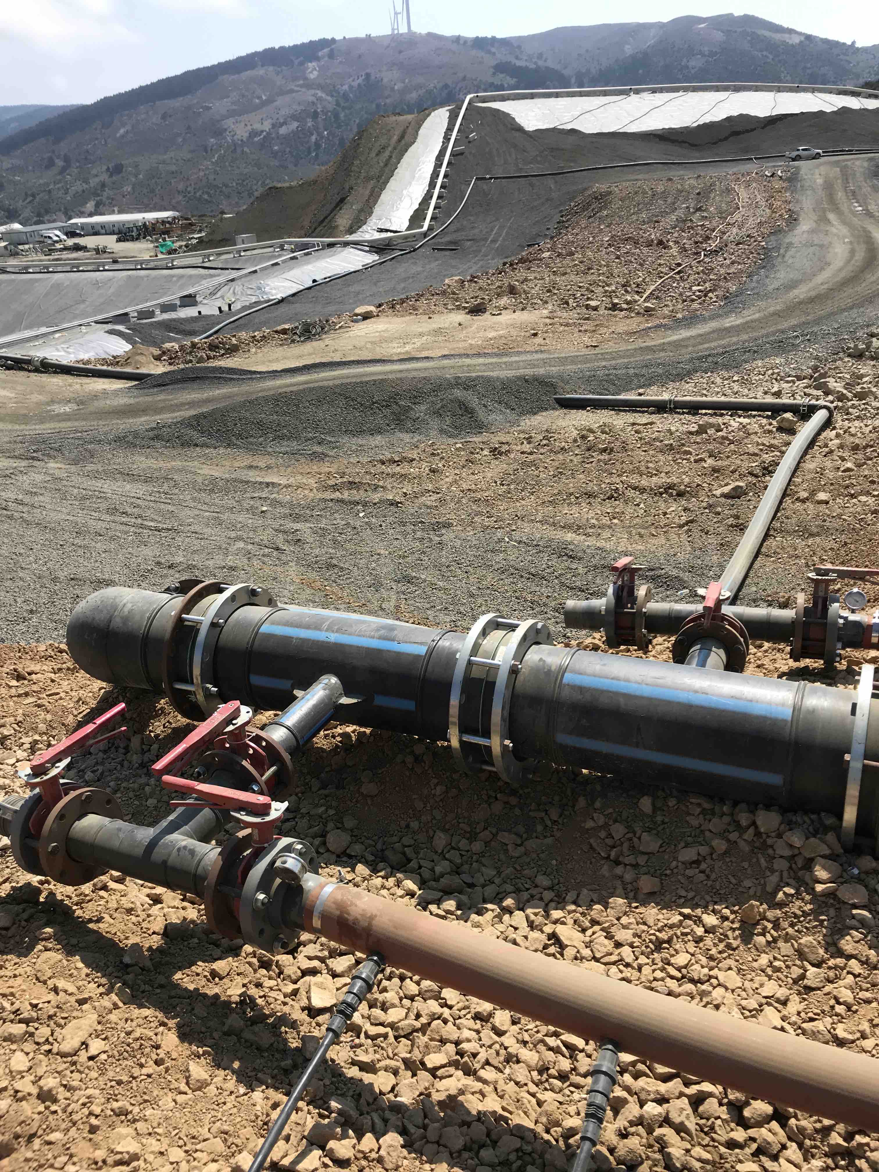
Step 4
Once your project data is gathered, send it to our team for a free engineering review, system design, and detailed quotation.
Share pad geometry, ore characteristics, application targets, water chemistry, and site layout. Use the consultation form or send to your Ore-Max contact.
Our engineers evaluate your inputs, identify any data gaps, and follow up with targeted questions before starting the hydraulic model.
We produce a complete hydraulic model with zone-by-zone pressure and flow, plus a detailed bill of materials covering every component from pump to end plug.
You receive a comprehensive quote, delivery schedule, and installation guidance — ready to share with procurement and your contractor.
Continue learning about heap leach distribution design before requesting a quote.
How Ore-Max engineers approach hydraulic layout, component selection, and field support.
Flow curves, pressure ratings, and performance data for Ore-Max emitter products.
Why drip irrigation outperforms sprinklers for heap leach applications.